1. Product analysis:
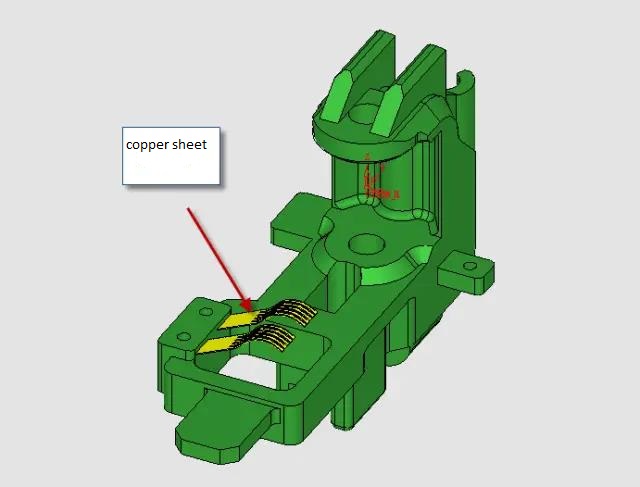
This case is for a bracket on the sensor of a car. The precision requirement is very high, the material is POM, the product is very small, the longest size is 38mm, and the metal insert (copper sheet) should be put when injection molding, and the deformation amount is very small, see Figure below.
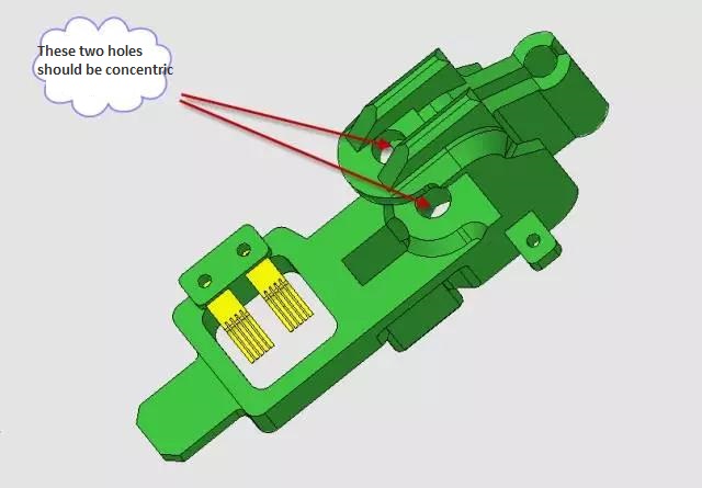
The upper and lower two holes of this product is not concentricity is under 0.02 mm, because POM products are prone to deformation, so in order to minimize the internal stress of products, into plastic point location selected in the mold design is to fully consider, and upper and lower two holes to finalize the design after the mold processing, as shown in figure below.
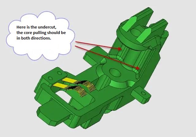
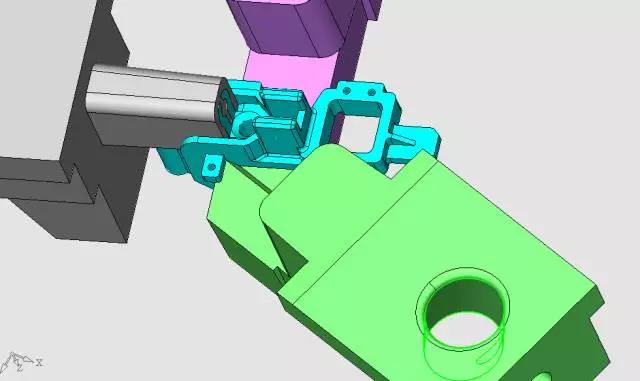
In the middle gap of the upper and lower two holes is reversed, and to pull the core in two directions can be out of the mold, which brings some difficulties to the design of the slider, see Figure below.
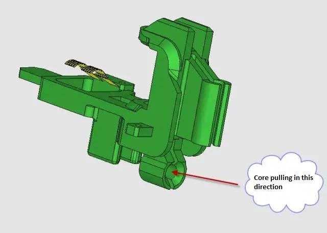
This direction should also be core-pulled, as shown in figure below.
In the injection molding to put a insert into the moving mold, the insert is a very elastic copper sheet, see figure below.
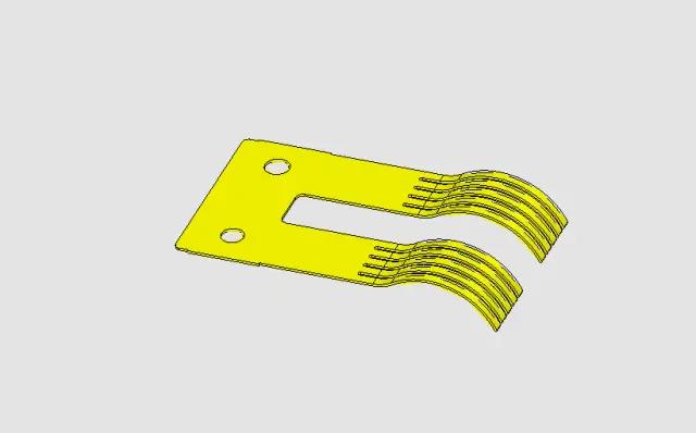
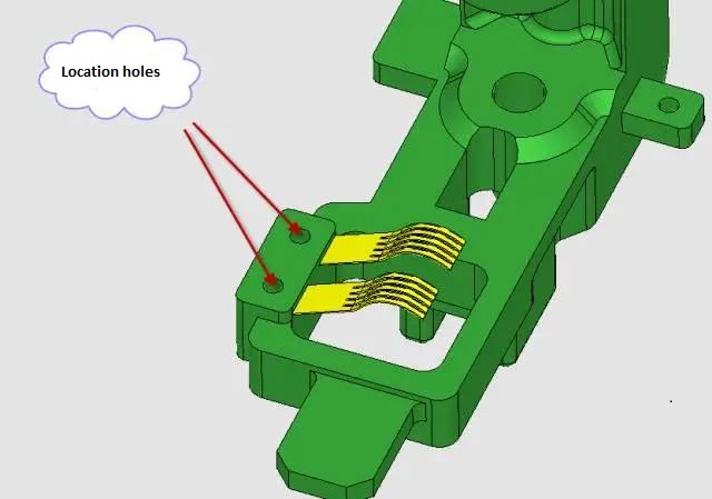
In order to prevent the copper sheet from being deflected by the plastic during injection molding, two small holes are set on the copper sheet, and the corresponding core is set in the mold to locate it, as shown in figure below.
2. Gate design:
After analysis, in order to reduce the stress of the product and reduce the deformation as far as possible, the best position of the plastic material entry point is here, as shown in figure below.
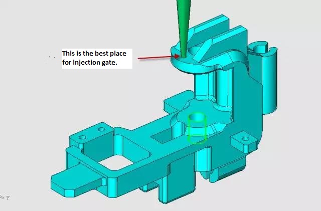
We took the form of a point gate, as shown in figure below.
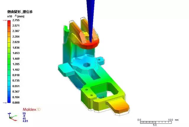
The mold flow analysis was provided by Moldex 3D, as shown in figure below.
Due to the tight space position, the gate we designed interfered with the fixed die insert, which was very difficult to deal with. Therefore,we canceled the fixed die insert and used thesolid block to form the core of the fixed die perforation, as shown in figure below.
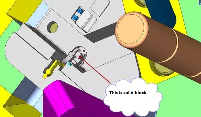
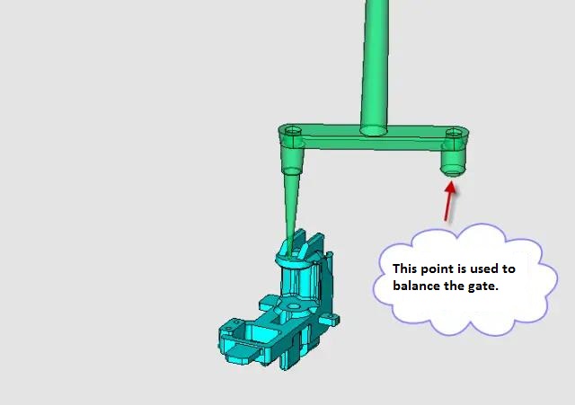
This allows a reasonable position for the gate pull rod, as shown in figure below.

The overall structure of the mold is a simplified small nozzle structure, and the first reset device is adopted, as shown in figure below.
3. Parting line:
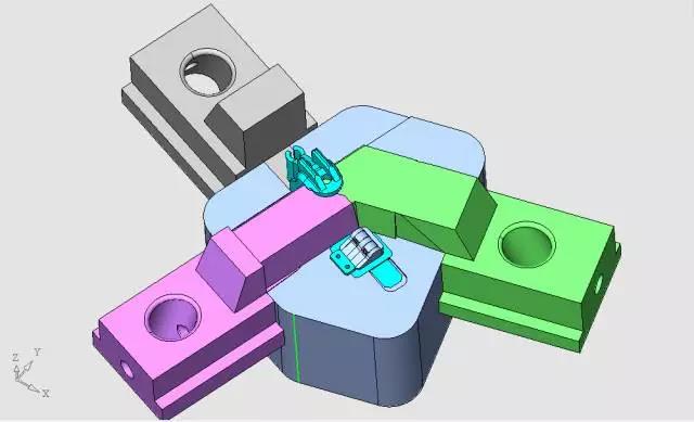
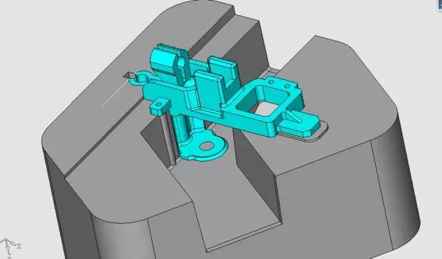
Thecore insert and three sliders are arranged in this way, as shown in figure below.
This is the reverse of the hiddencore side, as shown in figure below.
The cavity insert is designed like this, see figure below.
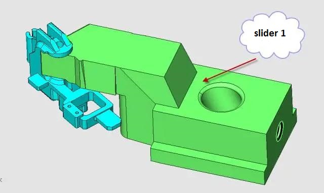
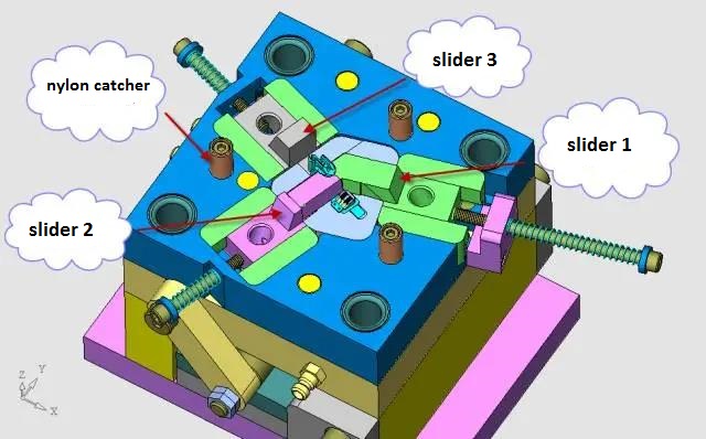
4.The design of the slider:
This molds looks not complicated, but the slider design is a little difficult, to take care of all aspects of the relationship. Start with slider 1, as shown in Figure below.
The relationship between slider 1 and slider 2 is shown in Figure below.
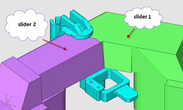
Because the slider 1 and slider 2 and their common boundary is the sealing surface, so here to be processed into a unified plane, and there should be adraft angle, in the fixedmold into insertion and penetration. And the mating surface should be made very precise, so that the joint line on the surface of the product should be as small as possible, as shown in Figure below.
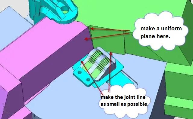
All mating surfaces where the sliders are inserted into the mold coreshould bemade slop in the direction of motion to avoid scratch marks caused byfriction between the sliders and the moldcore, as shown in Figure below.
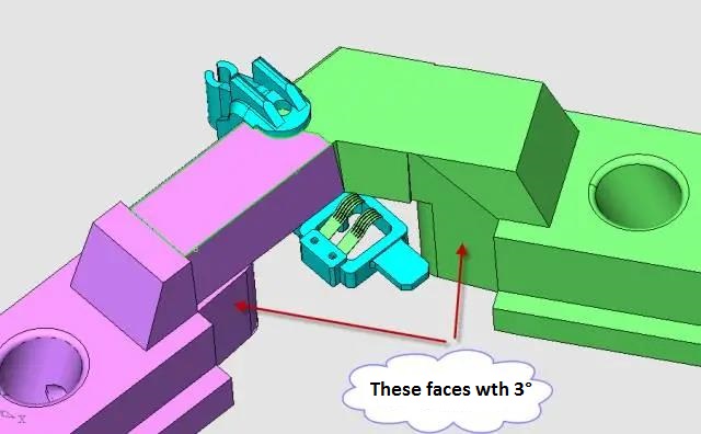
For the design of slider 3, see Figure below.
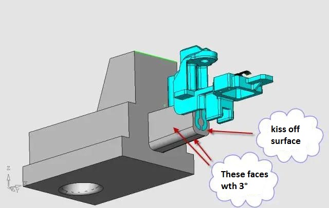
The end face of the slider 3 is touched through with the moving moldcore to form a sealing position. The mating surface of the moldcore is inclined to 3° in the direction of motion, so as to ensure that the slider will not have scratch marks due to friction during long-term work.
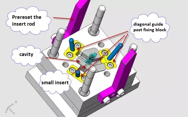
5. The design of fixed side of mold (cavity side):
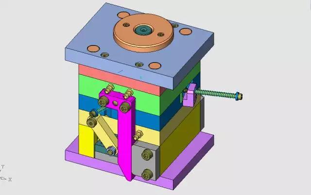
The power source of the sliding block is that the sliding block is removed by the force of the injection molding machine opening the mold by three inclined guide columns, and the inclined guide column is fixed on the fixed template by using the inclined guide column fixing block. The fixed die side is provided with a inserting rod that first resets the structure, as shown in Figure below.
6. The design of moving side of mold (core side):
The mold structure is very compact, using the standard 1515 simplified small nozzlemoldframe, see Figure below.
This is the case after the mold is opened and before ejection, as shown in Figure below.
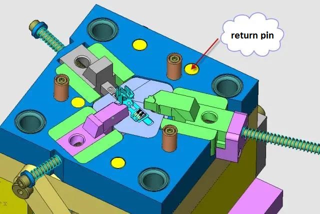
The force to pull the gate is dependent on the three nylon pull nails in the figure above. In order to balance the force of the reset, the position of the reset rod is also carefully designed.
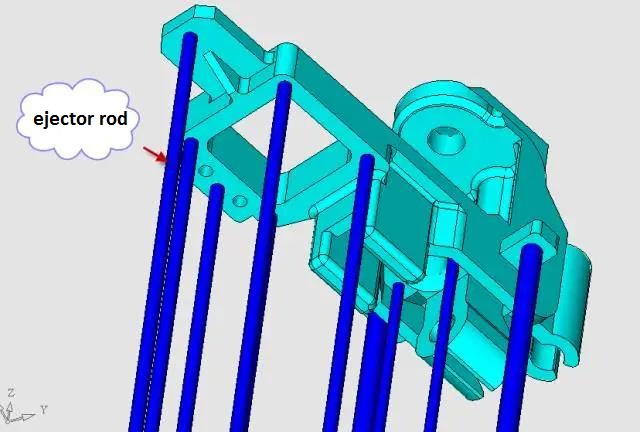
7. Design of ejection mechanism
In order to reduce the internal stress of the product and reduce the deformation to the minimum,we used more push rods, so that the top force of each part of the product is relatively balanced. A total of 10 pins were used, a rarity for such a small product, as shown in Figure below.
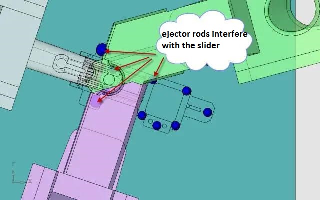
Since five of the ejector rods interfere with the slider, the reset structure must be set first, as shown in Figure below.
8. First reset mechanism design
Let me now introduce one of the most common pre reset mechanisms, as shown in Figure below.
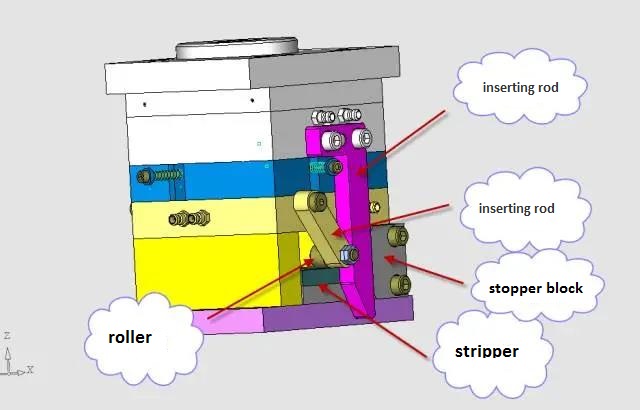
The pre reset mechanism, which is composed of four large pieces, namely the inserting rod, the pendulum rod, the roller and the block. When opening the mold, the oblique guide pillar will remove all the slider, as shown in Figure below.
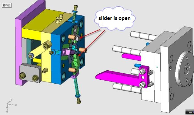
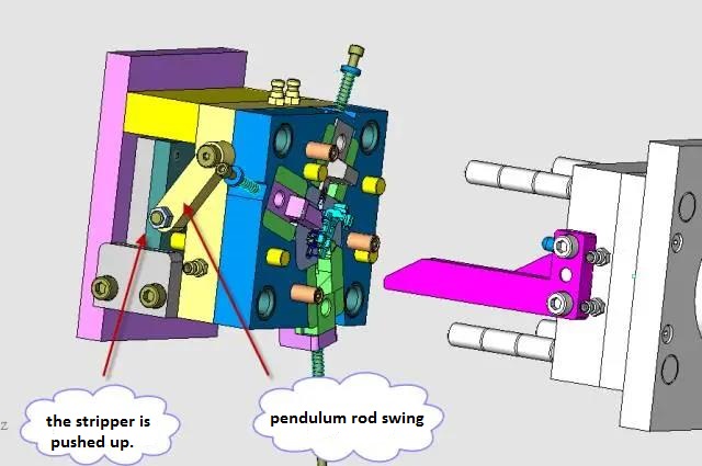
Since the insertion rod has been pulled out, the swing rod has room to rotate. When the top column of the injection molding machine pushes the push plate, the swing rod rotates along the pin shaft (15 degrees here) due to the action of the roller, as shown in Figure below.
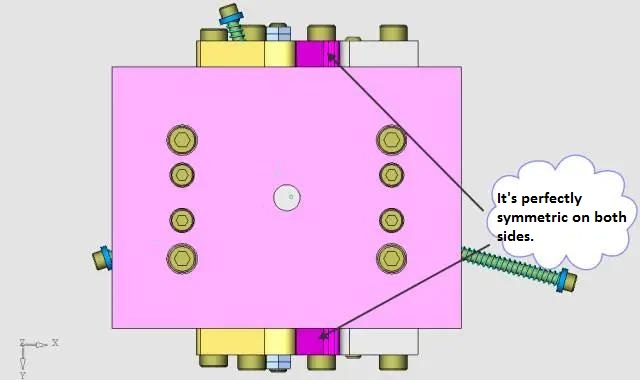
Thepre reset mechanism is completely symmetrical on both sides of the mold, as shown in Figure below.
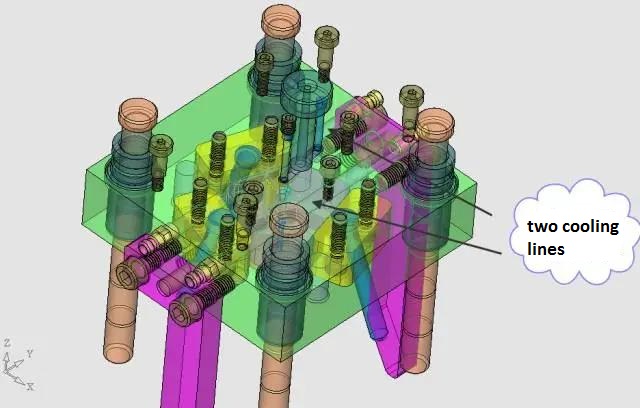
9. Design of cooling lines
Because the product is relatively small, and the injection gap to put inserts (copper), so the injection cycle is relatively long, so the mold cooling line is not high requirements,we adopted the most simplified design, because the mold core is relatively small, the water is directly from the template. The fixed mold is two straight water ways, as shown in FIG. below.
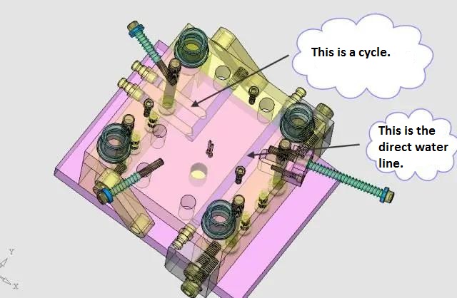
The same is true for the moving side, as shown in Figure below.
The key point of the design of this mold is the layout of the boundary of the slider 1 and the slider 2 and the choice of the position of the injection point.
What do you think about this precision mold design for the automobile sensor bracket? Welcome to comment together.