Product analysis
This product is a check valve used in solar water heater. The material is POM. See the figure below for its appearance.
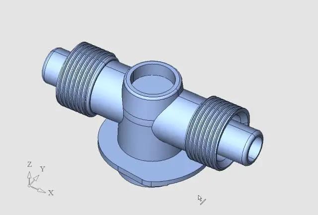
As you can see from the picture above, there are threads on the outside of the product. This is not difficult. There are internal threads on the back, and the central part is not rotatable, as shown below.
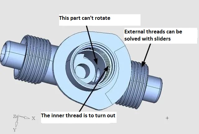
Demoulding of the product seems to be difficult because the middle part of the internal thread cannot be turned, but the internal thread must be mechanically turned out, and the middle part of the product is thicker, and the middle part of the internal thread must be cooled. These two requirements seem to contradict each other. It is an injection mold with a typical thread rotating core pulling structure, but the middle of the rotating part should be arranged as non-rotating, and the non-rotating part should be cooled. This case is a great challenge for the mold designer. The case comes from Green Vitality Industry Co., LTD.
Gate design
Before considering the mold structure,we should consider how to arrange the gate firstly. Because the product demoulding to four core pulling,it is difficult to make the mold with multi-cavities,can only considerto make this mold with a cavity. But the gate arrangement is more troublesome, generally speaking, this product has three kinds offeeding into the method: hot runner, points gate and direct gate. However,as the injection molding machine is relatively small, the total thickness of the mold is limited. From this point of view,we think thedirect gate is preferred, because the mold thickness of thedirect gate is the smallest.
Thedirect gate is the simplest, but where is thefeeding point? Due to the products to arrange gate in the best position is concave down, ordinarydirect gate will be difficult to achieve,runner cutting is difficult, if give updirect gate, do a point gate and hot runner, the moldwill bevery big, the height of obviously unreasonable, and mould cost also increased a lot, injection molding machine also will be need to use abigger tonnage, it directly increases the cost ofmassproduction, so theinjection way of directgate must be considered. After some consideration,we designa variation of thedirect gate, as shown below.
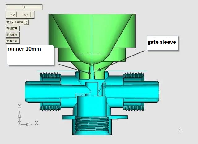
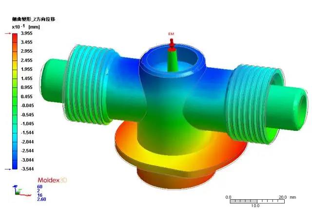
As can be seen from the figure above, the round boss with the round pit at the top of the molding product is made directly into a part of the gate sleeve,in this way,thetotal length of gate is10 mm, small end is 2.5 mm,large end is3 mm, at this time of the injection molding of least resistance and stripping resistance is the smallest,the gate is easy to remove, with the gate design, greatly simplifies thecavity side of the mould, The thickness of thecavity side is also greatly reduced, suitable for the production of smalltonnage injection molding machine and make room for thecore insert to arrange a reasonable demoulding mechanism. After mold flow analysis by Moldex 3D, the design of the gate is very reasonable, as shown below.
Design of thread core
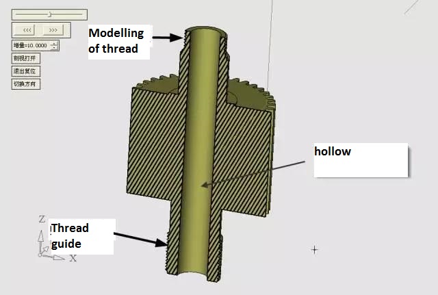
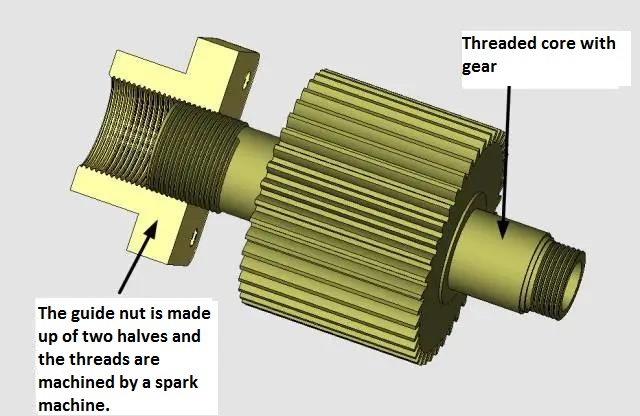
The thread core is hollow, in order to compact mold structure and enough strength of the thread core,we made the gear and thread core into one, the other end of the thread core has a guide thread, lead and modeling thread lead is consistent, see the following figure.
Guided threads are fitted with custom nuts. When the gear of screw thread core will be driving, the guide screw thread on the threaded core rotate at the same time, make the threaded core rotate while backward, because the nut is hardness, reasonable hardness is HRC48 ~ 52, in this kind of hardness, internal thread processing is difficult, for the convenience of processing and assembling,we make this nut can be divided into two halves. After finishing the two halves are installed in a corresponding hole to become a whole. Nuts are made of CrWMn, as shown below.
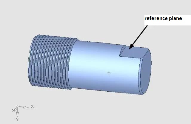
Threads are machined with electrodes. The electrodes of the nut threads are machined by a CNC lathe. The fixed end of the electrode is milling a datum surface, and when half of the nut is processed, the electrode is reversed and then marked in the center, and the other half of the nut is processed, as shown in the figure below.
The action principle of the whole mold
The demoulding of this mold isnot easy to understand, letus explain to you.
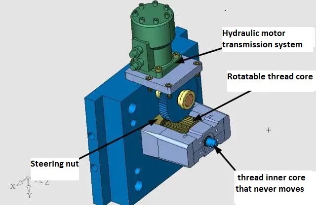
First step, before the mold is opened, the thread core is driven by the hydraulic motor to rotate and move along the guide nut, making this part of the thread from the product. At this time, the thread inner core is not moving, because the head shape of the thread inner core is non-rotary body, as shown below.
For the second action, the movingmold pad and the movingmold bottom plate are separated by 15mm first, as shown in the figure below.
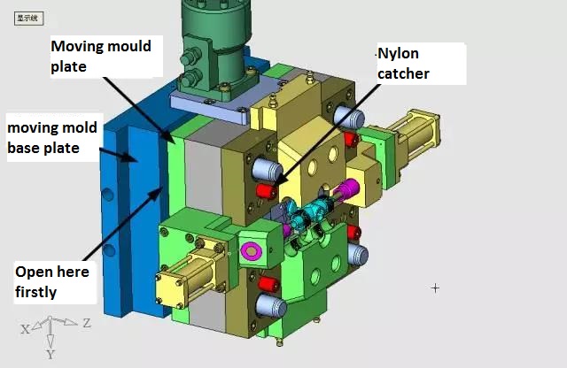
In the figure above, it can be seen that the thread part of the thread core has been spun out. Because the nylon pull nail is set on the parting surface, the main parting surface is not opened when the mold is opened, but 15mm between the moving mold bottom plate and the moving mold bottom plate. At this time, the 4 sliders are still tightly wrapped around the product and move forward 15mm together, making the non-rotatable part of the thread inner core detached. The main parting surface is then opened and the two large sliders are separated by the action of the bevel guide column.
The third action is that the hydraulic cylinders on the two sides of the mouldpull out the mould core on the two sides, as shown in the figure below.
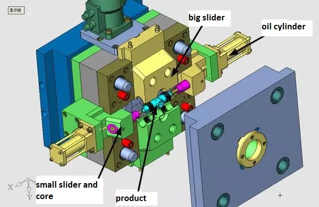
As the mold openingof thefirsttimeis only 15mm, the product has been released from the inner core of the thread, but there are parts of the inner core of the thread extended in the middle of the product. This will make the slider apart when the product will not stick to the slider, if the second action is much more open, so that the inner core of the screw thread core does not rotate completely leave the product, the product may be in the cylinder to pull the two sides of the core, with the core movement, that is, stick to the core, manipulator can not clip the product. The fourth action is to take out the product with the manipulator. The whole four movements are continuous.
The design of thecore mold
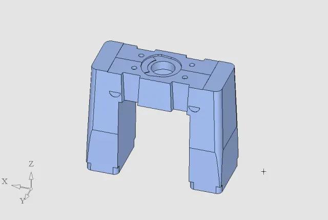
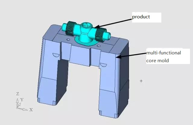
The core of the idea of this mold is thecore mold. Whenwesay thecoremold here,wedon't mean the whole moving mold part, but a single part. We have never seen before,wehave not designed such a part, it is not a moving mold, but it also participates in the molding, it is the core of the mold structural parts,wedo not know how to name it, but this is a "fantastic idea". We call it multifunctionalcore mold for short. Its shape is a bit like the French Arc de Triomphe, symbolizing the victory ofthismold, as shown in the picture below.
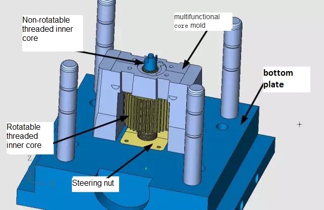
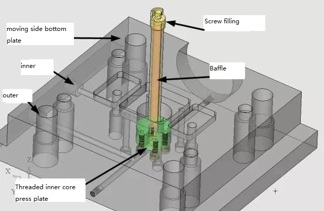
Its assembly in the moving moldpart is like this, as shown in the figure below.
Why is this core mold wecall multifunctioncore mold, let's see how many functions it has.
1. modelingPart of thecore mold is for modeling. The bottom of the product is provided by this multi-functionalcore mold, as shown in the following figure.
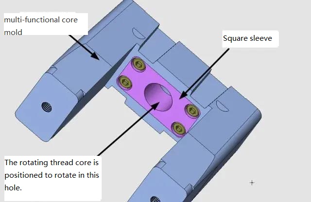
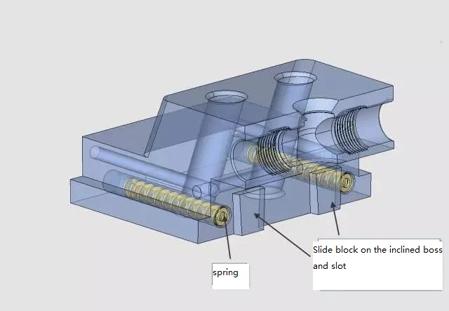
3. Position and limit the four sliders, as shown in the picture below.
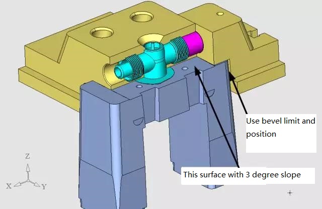
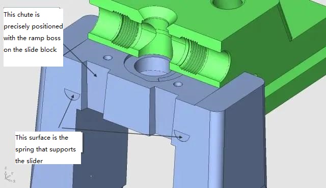
As mentioned above, in the second action of the mold, the active template and the moving mold bottom plate will be separated by 15mm. And soon is arranged on the active template, multi-function under themold is arranged on the bottom plate of the movingmold, that is to say, in this action, the slider will be separated from the multi-function under themold 15mm. When the mold is closed, the slider should return to the multifunctionalcore mold, which requires precise positioning between the slider and the multifunctionalcore mold, and it must be 3 sides with slope. We designed 4 sloped grooves on the multifunctionalcore mold, as shown in the picture below.
There are also corresponding oblique convex blocks on the slider, as shown in the figure below.
4. The precise positioning of the movable template and the moving mold base plate is shown in the following figure.
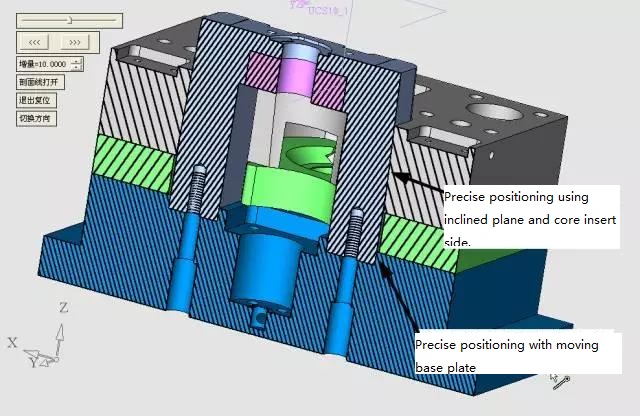
Can be seen in the image above, the dynamicmoving mold and dynamicmoving mold base plate is required for accurate positioning, but the mold of the second movement, the dynamic moving mold and dynamicmoving mold base is 15 mm apart, sowe brought multi-function near the bottom of thecore mold designed slope, and dynamicmoving mold of the inside of the inclined plane precision, already so when clamping precision positioning. Moreover, there is no friction with the multi-functionalcore mold when the movingmold is separated.
The multifunctionalcore mold is fixed on the bottom plate of the movingmold, as shown below.
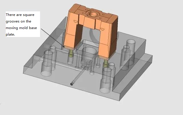
As can be seen from the figure above, the square groove on the bottom plate of the moving mold and the two squares at the bottom of the multifunctional core mold are precisely matched, so as to ensure the precise coordination between each part of the whole moving mold part, and when the active moving mold is separated by 15mm, there is no mold loss caused by friction.
5. Multifunctionalcore mold and slider bottom, see the picture below.
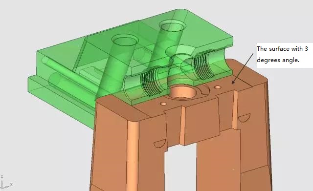
As can be seen in the figure above, the joint surface of the bottom surface of the slider and the upper part of the multifunctionalcore mold is inclined by 3°. This is a very important detail. The bottom surface of the slider is shaped, if there is no slope of the bonding surface, the bonding surface will wear quickly, lead to flashes on the product.
Why does it wear out so quickly? The reason is very simple, the locking of the sliding block is by the locking block on the fixed mold to the inclined surface of the sliding block when the mold is squeezed. Downward pressure on the extrusion force produces, slide block bottom and the top of the multi-functioncore mold extrusion, if the opposite and movement direction is parallel, creates friction, since the size of the friction force are determined by the positive pressure and friction coefficient, so this is from injection molding machine clamping force conversion pressure produced by the friction force is very big, so in this case, wear on the bottom surface of the slider and the multifunctionalcore mold will be quick.
Now wedesign the opposite slope, the situation is completely different, in the process of slider movement, the opposite is empty, only in the last moment of injection molding machine locking, the opposite was met, if the mold is accurate, let the opposite leave 0.008mm, used to exhaust, it is better, can completely avoid wear.
It can be seenAll of these,that the role of the multifunctionalcore mold in the whole mold is very important.
Design of threaded inner core
The inner core of the thread can not be rotated. It is demoulded by the relative movement of the moving mold and the bottom plate of the moving mold. The power is generated by the nylon nail. It is fixed to the bottom plate of the moving mould, because the part of the product facing the threaded inner core is very thick, so the threaded inner core must be adequately cooled. Here's howwedesigned it. See the picture below.
For easy assembly, the pressure plate of the threaded inner core is divided into two halves, fixed by 4 inner hexagon screws. In order to prevent the inner rotation of the thread, the steps of its last end are made into two small planes, as shown below.
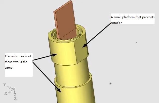
As can be seen from the above figure, the bottom of the thread inner core for easy assembly, the diameter of the second section of the outer circle is consistent, otherwise it can not be passed through the thread core, so that the position of the bottom of the thread inner core is very tight, the layout of the "O" type sealing ring is very troublesome,wedesign a copper sealing ring here, see the following figure.
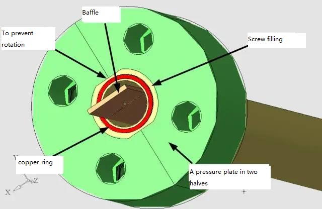
The copper seal ring is a good tool for this purpose. It is 0.1 higher than the underside of the threaded inner core and acts as a seal when the screw is tightened.
Large slider design
The design of the large slider is shown below.
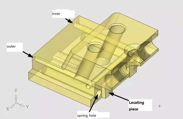
The design of the large slider is traditional, butwe have placed two positioning blocks here, which are original, but recycled anyway. But it's stuck in a multifunctional core mold that allows precise positioning and reduces friction between the large slider and the track.
As mentioned before, the movingmold bottom plate and the movingmold due to the action of nylon nail, will be separated by 15mm, and all the slider is arranged in the movingmold, that is to say,there is a 15mmrelative movement betweenthe sliderand themultifunctional core mold before mold opening.so, draft angle of the positioning block on the slider is small onthe bottom and big on the top.
Small slider core pulling design
The small slider is pulled by the cylinder, as shown in the picture below.
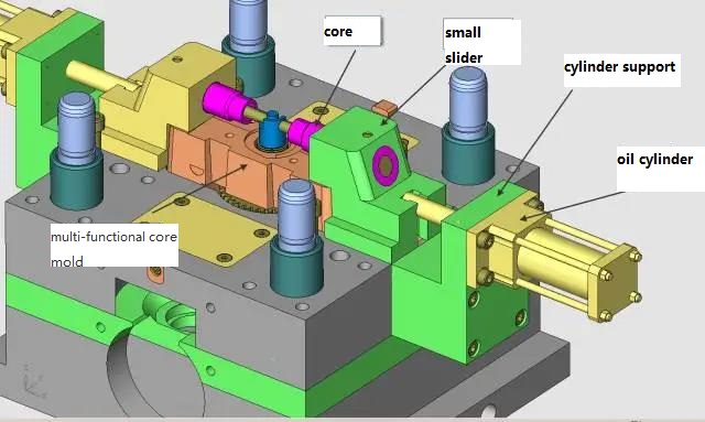
As can be seen from the figure above, the core is driven by a small slider, and the small slider is pulled by the cylinder mounted on the cylinder rack, which is relatively simple and traditional.
Design of transmission mechanism for rotating core-pulling
The design of the transmission mechanism of thread rotation core-pulling is shown in the figure below.
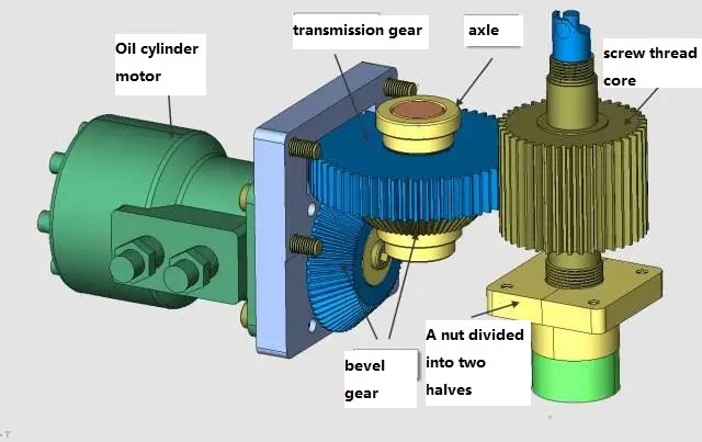
Can be seen in the image above, the oil motor drive with a pair of bevel gear, bevel gear and the second is coaxial transmission gear, gear drive gear on the threaded core, make the threaded core rotate, due to the lower end of the threaded core thread guide, the guide screw pitch and pitch (has put the shrinkage rate) on the product is consistent, So the threaded part of the shape on the threaded core will spin out of the product. The gear on the threaded core is thicker because it moves up and down.
Summary of highlights of this case:
1. The thread core does not turn the core (thread core) design is very characteristic, especially its fixing method is very good, but also the function of check. The copper sealing ring on the reverse side of the thread inner core is also of great practical value.
2. The lower end of the thread core is divided into two halves of the nut practice is very practical, the processing method is very simple.